
MB8 SERIES CNC HYDRAULIC PRESS BRAKE MACHINE WITH DA69S 6-8 AXIS

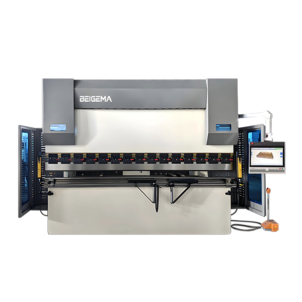
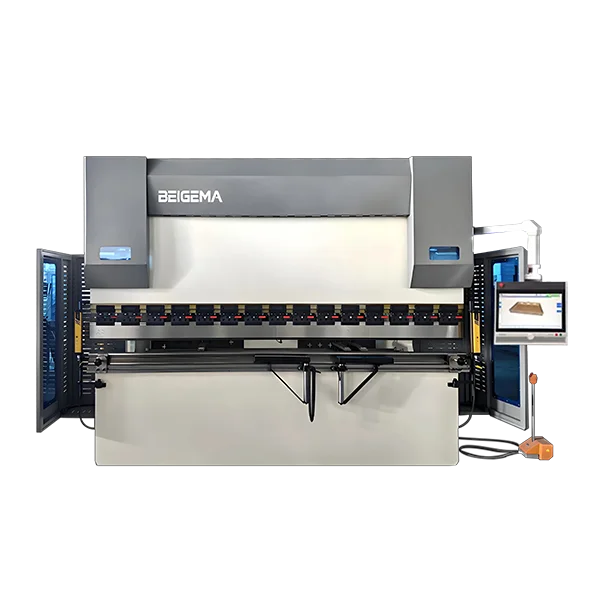
This MB8 configuration is centered on the Delem DA-69S control package for work that depends on 3D programming and visualization. The controller information published on this page includes 2D and 3D graphical touch programming, 3D visualization with machine representation, a 24-inch display, and Profile-S3D offline software. It is the MB8 controller page to assess for complex multi-bend parts and a more visual planning process.
Browse all CNC and NC hydraulic press brake machines, or see the economical WC67K NC press brake.
Configuration note: Controller, axes, working range, tolerances and included components must be confirmed in the signed technical quotation for the selected machine.
Why choose the DA-69S configuration: Delem positions the DA-69S as its 3D modular DA-60S control, with 2D and 3D graphical programming, 3D visualization, a 24-inch touch display and Profile-S3D offline software. This is the 3D-programming option among the three MB8 controller pages; confirm the supplied axes, software and optional interfaces in the technical quotation. See the official Delem DA-69S overview, compare the DA-66S MB8 model, or use our press brake selection guide.
Buyer resources: compare press brake machines, learn how to choose a press brake, or compare CNC and NC press brakes.
For a DA-69S demonstration, supply a representative 3D part and the intended punch and die arrangement. Ask to review the bend sequence and clearance around the actual machine configuration, and confirm which offline software functions and licenses are included in the offer.
- Model: MB8
- Controller: DA-69S
- Capabilities: 30T ~ 1000T
- NC Controller: DA-69S
- Back gauge: Y1+Y2+X+R
- Hydraulic valve: Rexroth from Germany
- Gear Pumu: Sunny from USA
- Foot Switch: Kacon from Korea
- Main Motor: Siemens from Germany
- Electric Components: Schneider from France
- Oil Sealing: Japan
- Ball Screw + Linear Guide: HIWIN
- Front Support: BEIGEMA
- Grating ruler: FAGOR
- Fast Clamp: BEIGEMA
- Punch and Die: Beigema
- Sealing ring: PARKER-UAS
- Compensation: Mechanical Crowning
Standard Configurations
Introduction To Components

DA-69S controller system
- 3D and 2D graphical touch screen programming mode
- 3D visualization, including 3D machine representation, in simulation and production
- 24″ high resolution color TFT
- Delem Modusys compatibility (module scalability and adaptivity)
- USB, peripheral interfacing
- User specific application support within the control’s multitasking environment
- Sensor bending & correction interface
- Profile-S3D offline software
For jobs that call for graphical programming in 3D, DA-69S supports both 3D and 2D touch-screen input. The DA-66S feature list describes 2D graphical programming, so the stated difference concerns how the job is programmed. Both descriptions include a 3D machine view during simulation and production; that display function alone does not distinguish these versions.
For a bending job with several tooling stations, the DA-69S service description covers a complete 3D machine setup for multiple tool stations. It also states automatic bend-sequence calculation and collision checking, with feedback on forming feasibility and the operating workflow. In the software comparison, the DA-69S product list names Profile-S3D for offline work, while the DA-66S list names Profile-S2D.

Standard Two V Die
The CNC double V-die features a dual-groove integrated design, allowing for quick switching without tool setting. It boasts high precision, wear resistance, and durability, ensuring smooth bending and positioning. Compatible with various CNC press brake machines, it produces high-efficiency, well-formed finished products — see the full range of press brake toolings.

Front Support Arm
Stable front support for large and long workpieces on the CNC press brake: the support plate is made of high-strength aluminum alloy profile, which has good load-bearing capacity and effectively prevents sagging and deformation when the plate is bent, ensuring the dimensional and angular accuracy of the workpiece and avoiding warping errors.

8+1 AXIS BACK GAUGE
The 8+1 axis press brake back gauge bends long and short plates, thick plates, and stainless steel with zero angular deviation from start to finish, eliminating the need for manual fine-tuning. It is suitable for complex multi-bending, and with 8-axis back gauge multi-directional positioning + W-axis compensation, it can form irregularly shaped, long, and large parts in one go, making it suitable for mass production of cabinets, new energy, chassis, and precision sheet metal.

Proportional Valve
Bosch Rexroth servo proportional valves offer closed-loop control, fast response, high accuracy (±0.01mm), high pressure resistance, durability, linearly adjustable flow rate, and compatibility with CNC press brake machines, providing stable operation, precise bending, and minimal maintenance.
Featuring high-frequency response, high closed-loop accuracy, shock resistance, long lifespan and steplessly adjustable flow rate, they work with the DA-66S/DA-69S system to ensure accurate bending angles, stable speeds, and low scrap rates.

Siemens Motor
The CNC press brake machine is equipped with an original Siemens CNC system and servo host, which features high precision, fast response, stable multi-axis synchronization, no drift over long periods, intelligent compensation, simple programming, and low failure rate, making it suitable for high-precision batch bending.

Servo Motor
- Rapid response, sensitive start/stop, smooth bending and speed change, fast processing rhythm
- Precise positioning, high accuracy in position and angle control, small finished product error
- Energy-saving and power-saving, low consumption under no-load, more fuel-efficient and power-saving than hydraulic systems
- Quiet operation, low vibration and noise, better workshop environment
- Durable and worry-free, sufficient torque and stable power, low failure rate and long service life
CNC Hydraulic Press Brake Machine DA-69S Specification
| Model | Bending Pressure (kN) | Bending Length (mm) | Column Distance (mm) | Throat Depth (mm) | Slider Stroke (mm) | Max Opening Height (mm) | X-axis Max Distance (mm) | Workpiece Linearity (mm/m) | Rear Gauge Precision (mm) | Back stopper (PCS) | Main Motor (kw) | Length*Width*Height (mm) | Weight (T) |
|---|---|---|---|---|---|---|---|---|---|---|---|---|---|
| 63T/1300 | 630 | 1300 | 1950 | 350 | 100 | 340 | 500 | ≥ 0.3 | 0.05 | 2 | 5.5 | 3100×1450×2050 | 5.8 |
| 63T/2500 | 630 | 2500 | 1900 | 350 | 170 | 380 | 500 | ≥ 0.3 | 0.05 | 2 | 5.5 | 3100×1450×2050 | 5.8 |
| 100T/3200 | 1000 | 3200 | 2700 | 400 | 200 | 420 | 500 | ≥ 0.3 | 0.05 | 3 | 7.5 | 3500×1580×2400 | 8.5 |
| 110T/3200 | 1100 | 3200 | 2700 | 400 | 200 | 420 | 500 | ≥ 0.3 | 0.05 | 3 | 7.5 | 3500×1580×2400 | 8.8 |
| 125T/3200 | 1250 | 3200 | 2700 | 400 | 200 | 420 | 500 | ≥ 0.3 | 0.05 | 3 | 11 | 3500×1580×2400 | 9.5 |
| 135T/3200 | 1350 | 3200 | 2700 | 400 | 200 | 420 | 500 | ≥ 0.3 | 0.05 | 3 | 11 | 3500×1580×2400 | 9.9 |
| 160T/3200 | 1600 | 3200 | 2700 | 400 | 200 | 420 | 500 | ≥ 0.3 | 0.05 | 3 | 11 | 3500×1650×2500 | 11 |
| 175T/3200 | 1750 | 3200 | 2700 | 400 | 200 | 420 | 500 | ≥ 0.3 | 0.05 | 3 | 11 | 3500×1650×2500 | 11 |
| 200T/3200 | 2000 | 3200 | 2700 | 400 | 200 | 420 | 500 | ≥ 0.3 | 0.05 | 3 | 15 | 3500×1680×2550 | 14 |
| 250T/3200 | 2500 | 3200 | 2700 | 400 | 200 | 420 | 500 | ≥ 0.3 | 0.05 | 3 | 15 | 3500×1700×2600 | 15.5 |
| 300T/3200 | 3000 | 3200 | 2700 | 400 | 200 | 420 | 500 | ≥ 0.3 | 0.05 | 3 | 22 | 3500×1800×2730 | 16.8 |
| 400T/4000 | 4000 | 4000 | 3500 | 400 | 320 | 420 | 500 | ≥ 0.3 | 0.05 | 4 | 30 | 4500×2450×3500 | 31 |
| 500T/6000 | 5000 | 6000 | 4900 | 500 | 320 | 600 | 800 | ≥ 0.3 | 0.05 | 6 | 37 | 6500×2810×4500 | 53 |
| 600T/6000 | 6000 | 6000 | 4900 | 500 | 320 | 600 | 800 | ≥ 0.3 | 0.05 | 6 | 45 | 6500×2910×5100 | 68 |
| 800T/6000 | 8000 | 6000 | 4900 | 600 | 400 | 600 | 800 | ≥ 0.3 | 0.05 | 6 | 55 | 6500×2950×5300 | 90 |
| 800T/8000 | 8000 | 8000 | 5900 | 600 | 400 | 600 | 800 | ≥ 0.3 | 0.05 | 8 | 55 | 8500×2950×5900 | 120 |
| 1000T/6000 | 10000 | 6000 | 4900 | 600 | 400 | 600 | 800 | ≥ 0.3 | 0.05 | 6 | 2×37 | 6500×3000×5600 | 100 |
| 1000T/8000 | 10000 | 8000 | 6900 | 600 | 400 | 600 | 800 | ≥ 0.3 | 0.05 | 8 | 2×37 | 8500×3000×6100 | 130 |
| 1000T/10000 | 10000 | 10000 | 8000 | 600 | 400 | 600 | 800 | ≥ 0.3 | 0.05 | 10 | 2×37 | 10500×3000×5850 | 150 |
| 1200T/6000 | 12000 | 6000 | 4900 | 600 | 400 | 800 | 1000 | ≥ 0.3 | 0.05 | 6 | 2×37 | 6500×3100×5850 | 130 |
| 1200T/7000 | 12000 | 7000 | 5900 | 600 | 400 | 800 | 1000 | ≥ 0.3 | 0.05 | 7 | 2×37 | 8500×3100×7150 | 160 |
FAQ
When should a buyer choose the DA-69S configuration?
The DA-69S version is the MB8 page to evaluate when 3D programming and visualization are central to the bending workflow. The published controller package supports both 2D and 3D graphical touch programming, 3D visualization with machine representation, a 24-inch display and Profile-S3D offline software. It is therefore the more suitable comparison point for complex multi-bend parts, setup planning and teams that want to review the programmed sequence visually before production.
This controller capability should not be confused with a fixed machine build. The DA-69S can sit on different MB8 configurations, so the signed quotation must still define working length, tonnage, back-gauge axes, compensation, tooling and safety equipment. A 3D controller is useful only when the supplied machine, tooling data and operator workflow are configured around the actual parts.
What information should accompany a DA-69S enquiry?
- Part drawings, material, thickness, bend length, bend sequence and annual or batch volume.
- Required axis movements, part-support needs and the intended offline-programming workflow.
- Punch and die requirements, crowning method, guarding and any angle-measurement option.
- Acceptance tolerances, target cycle considerations and the items that must be included in commissioning.
Before locking the frame and tooling, use the bending force calculator on material, thickness, bend length and V opening.
If the production mix is mainly handled with 2D graphical programming, review the DA-66S MB8 configuration. The E21, DA-53T, DA-66S and DA-69S comparison explains the controller levels, while the quotation form collects the machine details needed for a final match.
How the DA-69S supports 3D-oriented bending work
The DA-69S workflow is designed around creating and checking the part in a graphical environment before it reaches production. Its published 2D and 3D programming functions let the operator work with the part geometry, while the 3D machine visualization helps review the bend sequence in the context of the press brake. Profile-S3D extends that preparation to an offline workstation, which is useful when programming time needs to be separated from machine time.
This capability is especially relevant for parts with several bends, difficult handling positions or sequences that deserve visual review before setup. It does not remove the need to define the physical machine. The signed quotation must still identify tonnage, working length, actual axes, back-gauge travel, compensation, tooling, part support and the safety package.
Information needed for a DA-69S project review
- Part files or drawings showing the complete bend sequence, material, thickness and bend length.
- The tolerances, batch volume and setup constraints that make 3D planning valuable.
- The required back-gauge movements, tooling data, crowning method and part-support equipment.
- The intended Profile-S3D workflow, commissioning scope and operator-programming requirements.
BEIGEMA can use those inputs to confirm whether the 3D-oriented DA-69S package is justified or whether the 2D-focused DA-66S configuration is the closer fit. The controller comparison guide provides the wider E21, DA-53T, DA-66S and DA-69S context before a technical quotation is prepared.