
Short answer: the press brake tonnage chart is a catalog of published tonnage steps and bed lengths, not a force calculation. Use it to shortlist models by tonnage and bed length, then confirm the actual force for your material, thickness and V opening with a separate calculation. The buyer decision sequence runs from part requirements to catalog shortlist, then to force review, then to a signed technical quotation that fixes the configuration.
Start with the part: material grade, thickness range, maximum bend length, and the smallest inside radius the drawing allows. Those four items decide which tonnage steps and bed lengths are even worth opening in the catalog.
Next, separate what the buyer supplies from what the seller confirms.
The acceptance part demonstrates the agreed configuration on a real workpiece. It shows that the selected model, tooling and controller can produce the drawn part within the tolerances written into the quotation.
How to read the press brake tonnage chart
The chart below collects published tonnage steps and bed lengths by series. Read it as a catalog index. Each row is a tonnage step; each cell lists the bed lengths built for that step in that series. A dash means the series does not publish that step in the catalog, not that the step is impossible to build. Tandem cells list the bed lengths built per frame, so a tandem row describes a pair of frames, not a single machine.
| Tonnage step | Rated force (kN) | WC67K NC hydraulic | MB8 CNC hydraulic | Pure electric | Tandem pair |
|---|---|---|---|---|---|
| 35T | 350 | — | — | 1350 | — |
| 40T | 400 | 2200 / 2500 | — | — | — |
| 50T | 500 | 2500 | — | 1650 | — |
| 63T | 630 | 2500 / 3200 | 1300 / 2500 | 2050 / 2500 | — |
| 80T | 800 | 2500 / 3200 | — | — | — |
| 100T | 1000 | 2500 / 3200 / 4000 | 3200 | 2500 / 3200 | — |
| 110T | 1100 | — | 3200 | — | — |
| 125T | 1250 | 2500 / 3200 / 4000 | 3200 | — | — |
| 135T | 1350 | — | 3200 | — | — |
| 160T | 1600 | 3200 / 4000 / 5000 / 6000 | 3200 | — | — |
| 175T | 1750 | — | 3200 | — | — |
| 200T | 2000 | 3200 / 4000 / 6000 | 3200 | — | — |
| 250T | 2500 | 3200 / 4000 / 6000 | 3200 | — | 2*250T: 4000 / 5000 / 6000 |
| 300T | 3000 | 3200 / 4000 / 6000 / 7000 | 3200 | — | — |
| 320T | 2*3200 | — | — | — | 2*320T: 3200 / 4000 / 5000 / 6000 |
| 400T | 4000 | 6000 | 4000 | — | 2*400T: 3200 / 4000 / 5000 / 6000 |
| 500T | 5000 | 6000 | 6000 | — | 2*500T: 4000 / 5000 / 6000 |
| 600T | 6000 | 6000 | 6000 | — | — |
| 800T | 8000 | — | 6000 / 8000 | — | — |
| 1000T | 10000 | — | 6000 / 8000 / 10000 | — | — |
| 1200T | 12000 | — | 6000 / 7000 | — | — |
Units matter when you compare rows. The chart uses tonnage steps in tons and rated force in kilonewtons. The two columns describe the same step, so read them together rather than treating them as separate specifications.
Tandem notation needs its own reading. A model written as a pair of forces describes two frames linked for long plate work. The bed length in a tandem cell is the length built per frame, and the pair works together under a linkage control.
Use the chart to build a shortlist, then move to the force side. The press brake tonnage calculator handles the V-opening and material side, while this page handles model and bed length screening. Keeping the two steps separate avoids the common mistake of picking a tonnage step from the chart and assuming it fits a die and material it was never checked against.
WC67K NC hydraulic press brake tonnage: 40 to 600 ton steps
| Model | Nominal pressure (kN) | Table length (mm) | Throat depth (mm) | Ram stroke (mm) | Main power (kW) |
|---|---|---|---|---|---|
| WC67K 40/2500 | 400 | 2500 | 200 | 100 | 4 |
| WC67K 50/2500 | 500 | 2500 | 200 | 100 | 5.5 |
| WC67K 63/3200 | 630 | 3200 | 250 | 100 | 5.5 |
| WC67K 80/3200 | 800 | 3200 | 320 | 150 | 7.5 |
| WC67K 100/3200 | 1000 | 3200 | 320 | 150 | 7.5 |
| WC67K 125/4000 | 1250 | 4000 | 400 | 150 | 7.5 |
| WC67K 160/4000 | 1600 | 4000 | 400 | 180 | 11 |
| WC67K 160/6000 | 1600 | 6000 | 400 | 200 | 15 |
| WC67K 200/4000 | 2000 | 4000 | 400 | 200 | 15 |
| WC67K 250/6000 | 2500 | 6000 | 400 | 250 | 18.5 |
| WC67K 300/4000 | 3000 | 4000 | 400 | 250 | 22 |
| WC67K 300/7000 | 3000 | 7000 | 400 | 250 | 30 |
| WC67K 400/6000 | 4000 | 6000 | 400 | 250 | 30 |
| WC67K 500/6000 | 5000 | 6000 | 400 | 300 | 37 |
| WC67K 600/6000 | 6000 | 6000 | 400 | 300 | 37 |
Read the WC67K rows as catalog descriptions of frame size, bed length, throat depth, ram stroke and main power. They do not state which tooling is included beyond the standard set, and they do not state a safe tool load.
For buyers comparing NC and CNC options, the WC67K NC press brake with E21 controller page lists the standard configuration and optional parts. The press brake controller comparison helps separate NC positioning from CNC programming when the part mix includes many small batches. Neither page replaces the signed quotation for the selected model.
MB8 CNC hydraulic press brake: 63 to 1200 ton steps
The MB8 series is the CNC hydraulic line, with a controller that supports graphical programming and a multi-axis back gauge. Its published rows start at a smaller tonnage step and extend to the largest frames in the catalog. The table below gives one row per tonnage step from the MB8 spec table, including column distance and maximum opening where published.
| Model | Bending pressure (kN) | Bending length (mm) | Column distance (mm) | Throat depth (mm) | Slider stroke (mm) | Max opening (mm) | Main motor (kW) |
|---|---|---|---|---|---|---|---|
| MB8 63T/2500 | 630 | 2500 | 1900 | 350 | 170 | 380 | 5.5 |
| MB8 100T/3200 | 1000 | 3200 | 2700 | 400 | 200 | 420 | 7.5 |
| MB8 125T/3200 | 1250 | 3200 | 2700 | 400 | 200 | 420 | 11 |
| MB8 160T/3200 | 1600 | 3200 | 2700 | 400 | 200 | 420 | 11 |
| MB8 200T/3200 | 2000 | 3200 | 2700 | 400 | 200 | 420 | 15 |
| MB8 250T/3200 | 2500 | 3200 | 2700 | 400 | 200 | 420 | 15 |
| MB8 300T/3200 | 3000 | 3200 | 2700 | 400 | 200 | 420 | 22 |
| MB8 400T/4000 | 4000 | 4000 | 3500 | 400 | 320 | 420 | 30 |
| MB8 500T/6000 | 5000 | 6000 | 4900 | 500 | 320 | 600 | 37 |
| MB8 600T/6000 | 6000 | 6000 | 4900 | 500 | 320 | 600 | 45 |
| MB8 800T/8000 | 8000 | 8000 | 5900 | 600 | 400 | 600 | 55 |
| MB8 1000T/10000 | 10000 | 10000 | 8000 | 600 | 400 | 600 | 2×37 |
| MB8 1200T/7000 | 12000 | 7000 | 5900 | 600 | 400 | 800 | 2×37 |
The MB8 table shows how bed length and column distance grow with tonnage step. Column distance is the clear space between the frames, and it limits the part width that can pass through without interference.
For a CNC shortlist, the MB8 CNC press brake with DA-66S page describes the standard controller, back gauge and crowning arrangement. The How to Choose a Press Brake: RFQ and FAT Checklist guide is useful for comparing NC and CNC priorities before you open the chart. Keep the chart step and the controller choice as separate decisions; a larger tonnage step does not automatically bring a more capable controller.
Pure electric press brake: 35 to 100 tons, the smallest rows in the chart
The pure electric series occupies the small end of the catalog. Its published rows cover short beds and lower tonnage steps, and the table includes motor and average power columns that the hydraulic tables do not carry. Read those columns as catalog data for the drive arrangement, not as a guarantee about cycle time or energy cost on your parts.
| Model | Pressure (kN) | Length (mm) | Throat depth (mm) | Slider (mm) | Opening (mm) | Main motor (kW) | Average power (kW) | Weight (kg) |
|---|---|---|---|---|---|---|---|---|
| Electric 35T 1350 | 350 | 1350 | 200 | 180 | 430 | 2*8.6 | 1.1 | 4000 |
| Electric 50T 1650 | 500 | 1650 | 300 | 200 | 470 | 2*16 | 2.3 | 4800 |
| Electric 63T 2050 | 630 | 2050 | 300 | 200 | 470 | 2*21 | 2.6 | 6300 |
| Electric 63T 2500 | 630 | 2500 | 300 | 200 | 470 | 2*21 | 2.7 | 6800 |
| Electric 100T 2500 | 1000 | 2500 | 400 | 250 | 525 | 2*30 | 2.7 | 8500 |
| Electric 100T 3200 | 1000 | 3200 | 400 | 250 | 525 | 2*30 | 2.7 | 8800 |
The electric rows are the place to look when the part is short, the batch is repetitive, and the floor space is tight.
See the pure electric press brake page for the standard and optional parts, and the Small Press Brake: Fit, Utilities and Delivery Checks page when the shortlist is driven by bed length rather than force. A small frame is not a substitute for a force review; the electric series still needs the V opening and material checked before you commit.
Tandem press brake: 2*250T to 2*500T for plates longer than one bed
Tandem rows appear when a single bed cannot cover the bend length. The catalog prints these as pairs, and the table below gives representative model rows per force step. The tandem spec table does not print a separate bending-length column, so the length in each model row is the reference for the frame pair.
| Model | Bending force (kN) | Column distance (mm) | Throat depth (mm) | Stroke (mm) | Opening height (mm) | Main motor (kW) |
|---|---|---|---|---|---|---|
| Tandem 2*250T/4000 | 2*2500 | 3500 | 410 | 250 | 620 | 2*18.5 |
| Tandem 2*250T/6000 | 2*2500 | 5100 | 410 | 250 | 620 | 2*18.5 |
| Tandem 2*320T/3200 | 2*3200 | 2700 | 450 | 300 | 670 | 2*22 |
| Tandem 2*320T/6000 | 2*3200 | 5100 | 450 | 300 | 670 | 2*22 |
| Tandem 2*400T/4000 | 2*4000 | 3500 | 500 | 300 | 670 | 2*30 |
| Tandem 2*500T/4000 | 2*5000 | 3500 | 500 | 300 | 670 | 2*30 |
| Tandem 2*500T/6000 | 2*5000 | 5100 | 500 | 300 | 670 | 2*30 |
Tandem notation is easy to misread. A model written as a pair of forces describes two frames, each with its own rated force, linked for long plate work.
The tandem press brake for long plate bending page lists the standard controller and configuration notes. Read those notes before you treat a tandem row as a single-machine substitute. A tandem pair is a different machine architecture, and the acceptance part should demonstrate the linked mode you actually intend to run.
From the chart to a tonnage step: thickness, material and V opening
The chart gives you a step and a bed length. The force review gives you the tonnage needed for a specific bend. The two are not interchangeable. A catalog step that looks generous can still be too small once the V opening, material strength and bend length are applied, and a step that looks tight can be adequate for a narrow die and a short bend. The force review is where those variables meet.
Thickness and material set the force per unit length. A stronger material needs more force for the same thickness and V opening, and the die opening changes the force required. The press brake tonnage calculator is the place to run those numbers, and the bend allowance and bend deduction formulas help with the flat pattern that the force review depends on. Do not apply an arbitrary derating factor to a catalog step; use the calculator and confirm the result with the seller.
Tooling load is a separate check. The machine’s rated force does not tell you what the punch or die can safely take. The tool supplier’s safe load for the specific tool, and the load distribution across the bend length, must be confirmed before you run a heavy part.
Use the chart to build a shortlist table of your own. The blank record below is a working format; fill it with the model code and the catalog row, and leave unknown fields as an em dash until the seller confirms them. Unknown means unconfirmed, not zero.
| Record field | Buyer entry | Seller confirmation |
|---|---|---|
| Part number and drawing revision | — | — |
| Material grade and thickness range | — | — |
| Maximum bend length | — | — |
| Required inside radius and V opening | — | — |
| Catalog model code and tonnage step | — | — |
| Published bed length and column distance | — | — |
| Controller and axis configuration | — | — |
| Tooling interface and safe tool load | — | — |
| Acceptance part and inspection items | — | — |
Length filter: the WC67K 40/2500 row lists 400 kN and a 2500 mm table. That identifies a catalog candidate; the bend and tooling still need a force review.
Equal-force filter: the electric 100T rows list 1000 kN with either 2500 mm or 3200 mm length. Select the length against the drawing before comparing handling and configuration.
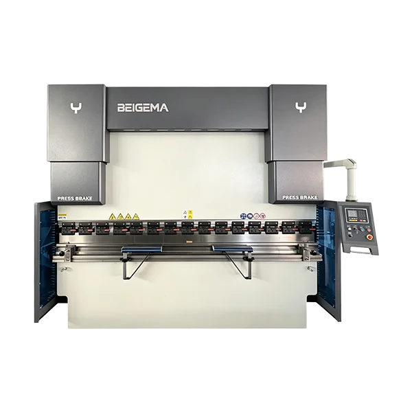
When the shortlist is ready, send the material and bend length for a force review and ask the seller to confirm the catalog row, the controller and axis set, and the tooling interface in writing. The press brake machine category page lists the series side by side, and the BEIGEMA press brake range gives the overall lineup. Keep the chart, the force review and the quotation as three separate documents; each answers a different question.
Press Brake Tonnage Chart FAQs
What is the difference between catalog tonnage and calculated tonnage? Catalog tonnage is the published rated force for a model row. Calculated tonnage is the force needed for a specific bend, based on material, thickness, V opening and bend length. The catalog tells you which steps exist; the calculation tells you whether a step is enough for the part. Use both, and confirm the result with the seller before you commit.
Does a longer bed change the tonnage I need? Bed length changes the machine you can use, not the force per unit length for a given bend. A longer bend spreads the load over more length, and the force review must use the actual bend length rather than the bed length. A long bed with a short bend does not need the full rated force, and a short bed with a long bend may not fit at all. Confirm the bend length and the load distribution with the seller.
How do I check tooling load against the chart? The chart lists machine force, not tool force. Ask the tool supplier for the safe load of the specific punch and die, and confirm that the load distribution across the bend length stays within it. Do not infer a tool’s safe load from the machine’s rated force. If the tool data is missing, treat it as unconfirmed and resolve it before running the part.
What does a tandem model code mean? A tandem code written as a pair of forces describes two frames linked for long plate work. The bed length in the tandem row is the length built per frame, and the pair can work independently or in sync only when the controller and linkage option are configured for it. Confirm the linkage arrangement and the acceptance part in the signed quotation; do not assume every tandem pair ships with the same control setup.
Air-bending force and V-die opening chart (V = 8×t reference)
Engineering selection conclusion: Before locking a catalog model row, screen the actual air-bending force per metre using F (kN/m) = 650 × t² ÷ V at the 450 MPa steel baseline with a standard V = 8×t die opening, where inside radius is IR ≈ V ÷ 6 and minimum flange length is 0.7 × V. Add a 20% planning reserve before matching a WC67K NC hydraulic press brake, MB8 CNC hydraulic press brake, or BEIGEMA press brake machine, and verify custom die widths in the press brake tonnage calculator.
| Plate thickness t (mm) | Standard V-die (mm) | Min flange 0.7×V (mm) | Inside radius IR ≈ V/6 (mm) | Base force (kN/m) | Base force (tf/m) | 3.2 m bed + 20% reserve (kN) | Catalog series step shortlist |
|---|---|---|---|---|---|---|---|
| 1.0 | 8 | 5.6 | 1.3 | 81.3 | 8.3 | 312 | 35T Pure electric · 40T WC67K |
| 1.5 | 12 | 8.4 | 2.0 | 121.9 | 12.4 | 468 | 50T / 63T WC67K · 63T MB8 |
| 2.0 | 16 | 11.2 | 2.7 | 162.5 | 16.6 | 624 | 63T / 80T WC67K · 63T / 100T MB8 |
| 3.0 | 24 | 16.8 | 4.0 | 243.8 | 24.9 | 936 | 100T WC67K · 100T MB8 |
| 4.0 | 32 | 22.4 | 5.3 | 325.0 | 33.1 | 1,248 | 125T / 160T WC67K · 125T / 135T MB8 |
| 6.0 | 50 | 35.0 | 8.3 | 468.0 | 47.7 | 1,797 | 200T WC67K · 200T MB8 |
| 8.0 | 63 | 44.1 | 10.5 | 660.3 | 67.3 | 2,536 | 300T WC67K · 300T MB8 |
| 10.0 | 80 | 56.0 | 13.3 | 812.5 | 82.9 | 3,120 | 300T / 400T WC67K · 300T / 400T MB8 |
| 12.0 | 100 | 70.0 | 16.7 | 936.0 | 95.4 | 3,594 | 400T WC67K · 400T MB8 |
| 16.0 | 125 | 87.5 | 20.8 | 1,331.2 | 135.7 | 5,112 | 600T WC67K · 600T MB8 |
| 20.0 | 160 | 112.0 | 26.7 | 1,625.0 | 165.7 | 6,240 | 800T MB8 (or wider V-die opening) |
Related selection reference: Ironworker Machine vs Separate Machines: Five Tradeoffs for Buyers. The WC67K NC press brake with E21 controller provides the supplier specification behind the shortlist.
Compare BEIGEMA press brake range against this job brief, then send your press brake tonnage chart requirements for a configuration review.
For factory specification sheets and controller configurations across this machinery series, compare our WC67K Series NC Hydraulic Press Brake Machine With TP10S Controller System.
Related pages
Related guides
- Press Brake Tonnage Chart: V-Die Opening, Material and Force
- Press Brake Tooling: European, American and New-Standard Systems Compared
- Bend Allowance and Bend Deduction for Accurate Flat Patterns
- Hemming, Gooseneck and Special Press Brake Tooling
- Press Brake Operation from Setup to First Part Inspection
- Press Brake Safety and Safeguarding
- How to Choose a Press Brake: A 7-Step Buyer’s Guide
- CNC vs NC Press Brake: Which One Do You Actually Need?
Machines this guide applies to
- MB8 Series CNC Hydraulic Press Brake Machine with DA-53Tx 4+1 Axis
- MB8 SERIES CNC HYDRAULIC PRESS BRAKE MACHINE WITH DA66S 6-8 AXIS
- MB8 SERIES CNC HYDRAULIC PRESS BRAKE MACHINE WITH DA69S 6-8 AXIS
- Pure Electric Press Brake Bending Machine
- Tandem Press Brake Machine for Long Plate Bending
- WC67K Series NC Hydraulic Press Brake Machine With E21 Controller System
- WC67K Series NC Hydraulic Press Brake Machine With E310P Controller System
- WC67K Series NC Hydraulic Press Brake Machine With TP10S Controller System